nrF24L01 无线控制舵机
1/7/2024 12:26:45 PM
1259
0
一、物料
- MG90S舵机x4
- 杜邦线若干
- arduino uno 开发板x2
- nrf24l01x2
- 5向摇杆x2
- 面包板x2
二、接线


1)nrf24l01接线
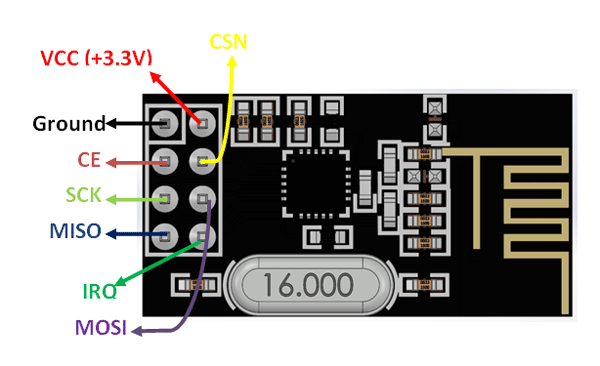
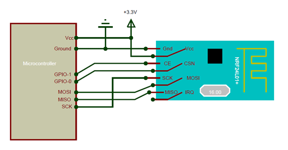
按照图示接线将 nrf24l01 接入arduino开发板对应的引脚。其中 CE / CSN可以自定义,IRO不用接线,其他的应按照对应引脚释义接入到开发板中
注意 :NRF24l01的工作电压范围是1.9-3.6伏特,所以其VCC不要接到5V的因脚上
2)舵机接线
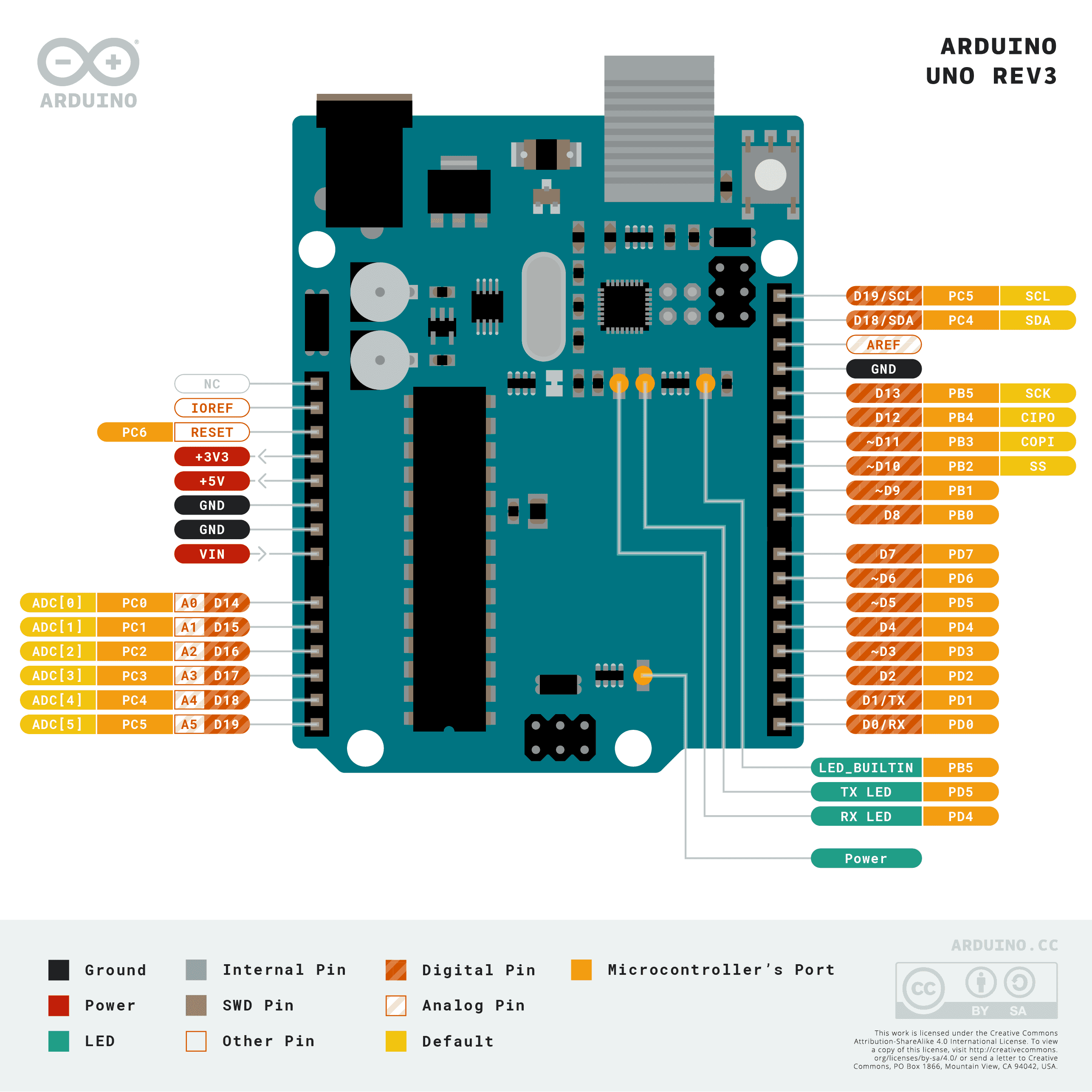
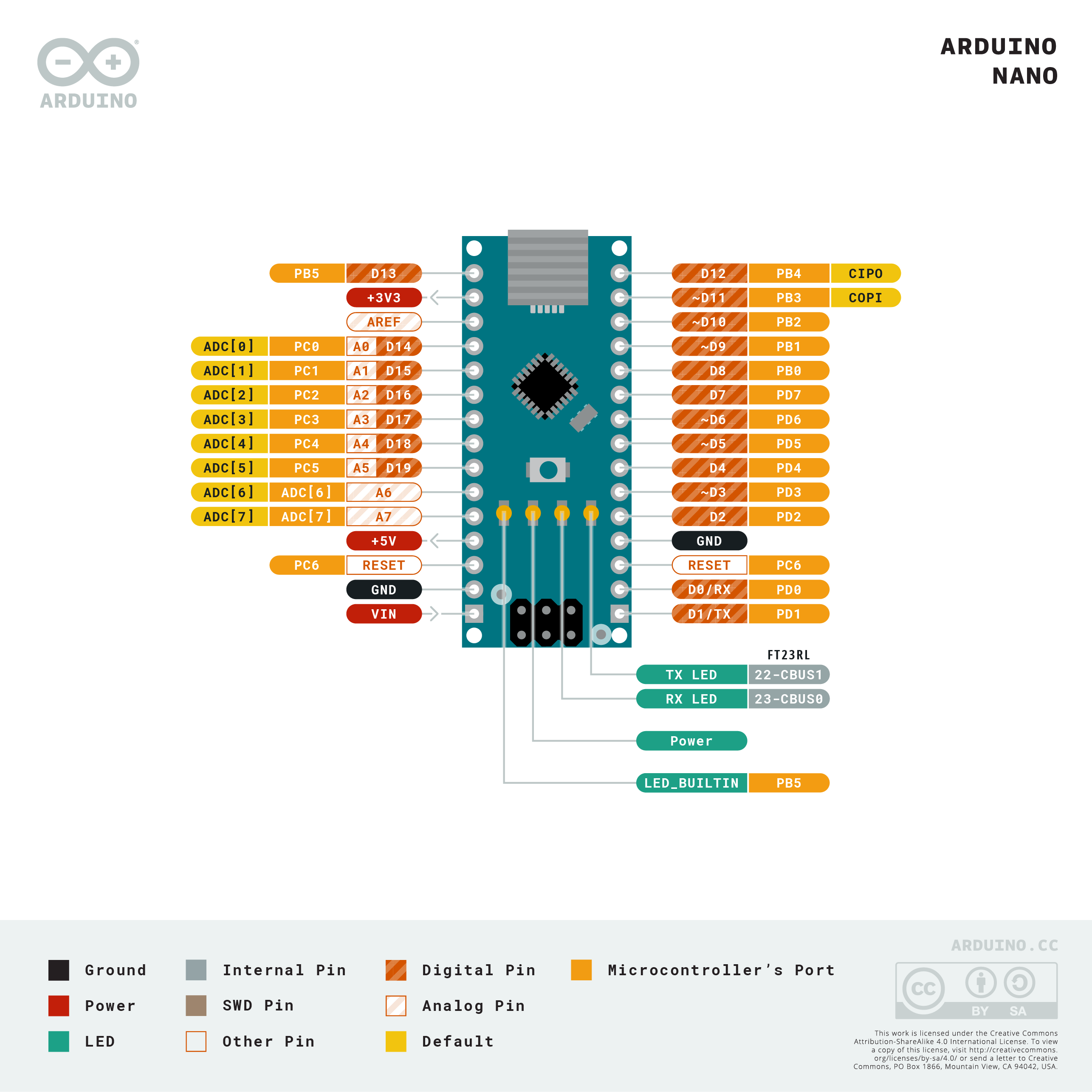
舵机有三根引线,橙色为信号控制线,红色为VCC,棕色为GND。在本示例中,四个舵机的橙色信号线分别接入接收端arduino uno的2、3、4、5四个IO口
3)摇杆接线
摇杆主要使用urx和ury 两个引脚来进行变量控制。两个摇杆的这两个引脚分别接入A0、A1、A2、A3四个模拟输入端口
三、代码部分
发送端
// 4 Channel Transmitter | 4 Kanal Verici

#include <SPI.h>
#include <nRF24L01.h>
#include <RF24.h>

const uint64_t pipeOut = 0xE9E8F0F0E1LL;  //IMPORTANT: The same as in the receiver 0xE9E8F0F0E1LL | Bu adres alıcı ile aynı olmalı
RF24 radio(7, 8);                         // select CE,CSN pin | CE ve CSN pinlerin seçimi

struct Signal {
  byte throttle;
  byte pitch;
  byte roll;
  byte yaw;
};

Signal data;

void ResetData() {
  data.throttle = 127;  // Motor Stop (254/2=127)| Motor Kapalı (Signal lost position | sinyal kesildiğindeki pozisyon)
  data.pitch = 127;     // Center | Merkez (Signal lost position | sinyal kesildiğindeki pozisyon)
  data.roll = 127;      // Center | merkez (Signal lost position | sinyal kesildiğindeki pozisyon)
  data.yaw = 127;       // Center | merkez (Signal lost position | sinyal kesildiğindeki pozisyon)
}

void setup() {
  //Start everything up
  Serial.begin(9600);
  radio.begin();
  radio.openWritingPipe(pipeOut);
  radio.stopListening();  //start the radio comunication for Transmitter | Verici olarak sinyal iletişimi başlatılıyor
  ResetData();
}

// Joystick center and its borders | Joystick merkez ve sınırları

int mapJoystickValues(int val, int lower, int middle, int upper, bool reverse) {
  val = constrain(val, lower, upper);
  if (val < middle)
    val = map(val, lower, middle, 0, 128);
  else
    val = map(val, middle, upper, 128, 255);
  return (reverse ? 255 - val : val);
}

void loop() {
  // Control Stick Calibration | Kumanda Kol Kalibrasyonları
  // Setting may be required for the correct values of the control levers. | Kolların doğru değerleri için ayar gerekebilir.

  data.throttle = mapJoystickValues(analogRead(A0), 524, 524, 1015, true);
  data.roll = mapJoystickValues(analogRead(A1), 12, 524, 1020, true);   // "true" or "false" for servo direction | "true" veya "false" servo yönünü belirler
  data.pitch = mapJoystickValues(analogRead(A2), 12, 524, 1020, true);  // "true" or "false" for servo direction | "true" veya "false" servo yönünü belirler
  data.yaw = mapJoystickValues(analogRead(A3), 12, 524, 1020, true);    // "true" or "false" for servo direction | "true" veya "false" servo yönünü belirler

  Serial.print(" throttle: ");
  Serial.print(data.throttle);
  Serial.print(" roll: ");
  Serial.print(data.roll);
  Serial.print(" pitch: ");
  Serial.print(data.pitch);
  Serial.print(" yaw: ");
  Serial.print(data.yaw);
  Serial.println();
  radio.write(&data, sizeof(Signal));
  delay(500);  // 延时1秒
}
接收端
//  4 Channel Receiver | 4 Kanal Alıcı
//  PWM output on pins D2, D3, D4, D5 (Çıkış pinleri)

#include <SPI.h>
#include <nRF24L01.h>
#include <RF24.h>
#include <Servo.h>

int ch_width_1 = 0;
int ch_width_2 = 0;
int ch_width_3 = 0;
int ch_width_4 = 0;

Servo ch1;
Servo ch2;
Servo ch3;
Servo ch4;

struct Signal {
  byte throttle;
  byte pitch;
  byte roll;
  byte yaw;
};

Signal data;

const uint64_t pipeIn = 0xE9E8F0F0E1LL;
RF24 radio(7, 8);

void ResetData() {
  // Define the inicial value of each data input. | Veri girişlerinin başlangıç değerleri
  // The middle position for Potenciometers. (254/2=127) | Potansiyometreler için orta konum
  data.throttle = 127;  // Motor Stop | Motor Kapalı
  data.pitch = 127;     // Center | Merkez
  data.roll = 127;      // Center | Merkez
  data.yaw = 127;       // Center | Merkez
}

void setup() {
  Serial.begin(9600);
  //Set the pins for each PWM signal | Her bir PWM sinyal için pinler belirleniyor.
  ch1.attach(2);
  ch2.attach(3);
  ch3.attach(4);
  ch4.attach(5);

  //Configure the NRF24 module
  ResetData();
  radio.begin();
  radio.openReadingPipe(1, pipeIn);

  radio.startListening();  //start the radio comunication for receiver | Alıcı olarak sinyal iletişimi başlatılıyor
}

unsigned long lastRecvTime = 0;

void recvData() {
  while (radio.available()) {
    radio.read(&data, sizeof(Signal));
    lastRecvTime = millis();  // receive the data | data alınıyor
  }
}

void loop() {
  recvData();
  unsigned long now = millis();
  if (now - lastRecvTime > 1000) {
    ResetData();  // Signal lost.. Reset data | Sinyal kayıpsa data resetleniyor
  }

  ch_width_1 = map(data.throttle, 0, 255, 1000, 2000);  // pin D2 (PWM signal)
  ch_width_2 = map(data.pitch, 0, 255, 1000, 2000);     // pin D3 (PWM signal)
  ch_width_3 = map(data.roll, 0, 255, 1000, 2000);      // pin D4 (PWM signal)
  ch_width_4 = map(data.yaw, 0, 255, 1000, 2000);       // pin D5 (PWM signal)

  // Write the PWM signal | PWM sinyaller çıkışlara gönderiliyor
  Serial.print(" servo1:");
  Serial.print(ch_width_1);
  ch1.writeMicroseconds(ch_width_1);

  Serial.print(" servo2:");
  Serial.print(ch_width_2);
  ch2.writeMicroseconds(ch_width_2);

  Serial.print(" servo3:");
  Serial.print(ch_width_3);
  ch3.writeMicroseconds(ch_width_3);

  Serial.print(" servo4:");
  Serial.print(ch_width_4);
  ch4.writeMicroseconds(ch_width_4);

  Serial.println();
  delay(500);  // 延时1秒
}
四、演示
扩展阅读:
NRF24L01入门:https://blog.nnwk.net/article/185
全部评论